Sure! Here’s a revised version with sections and the images placed within them, with raw markdown:
Design Process
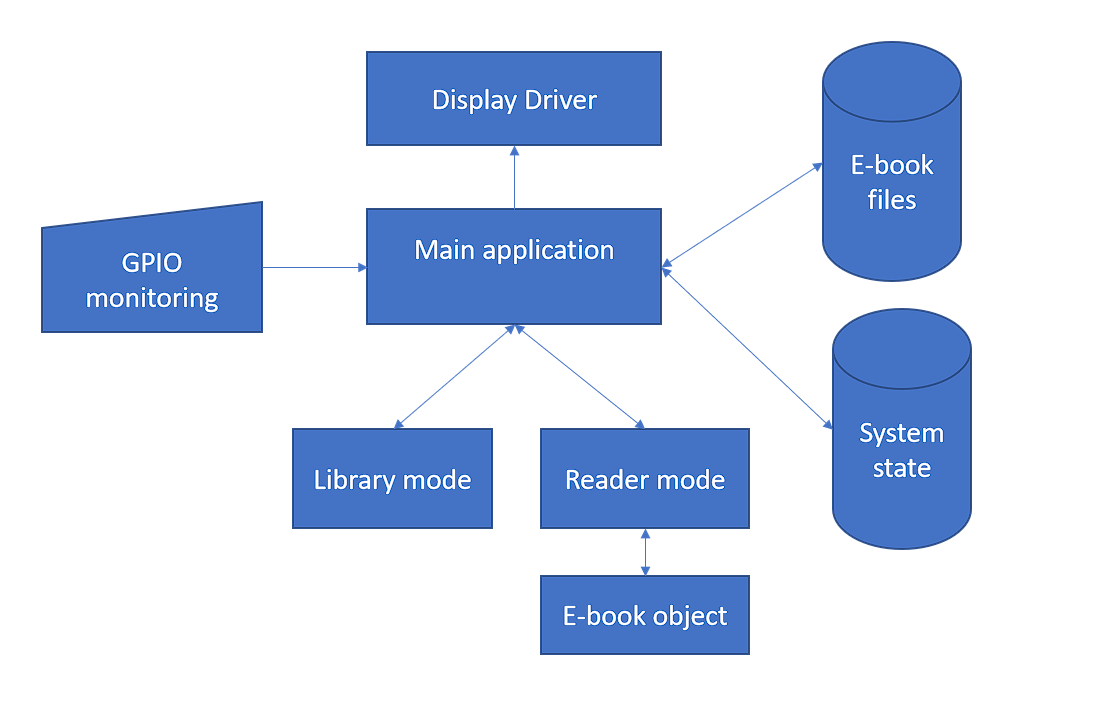
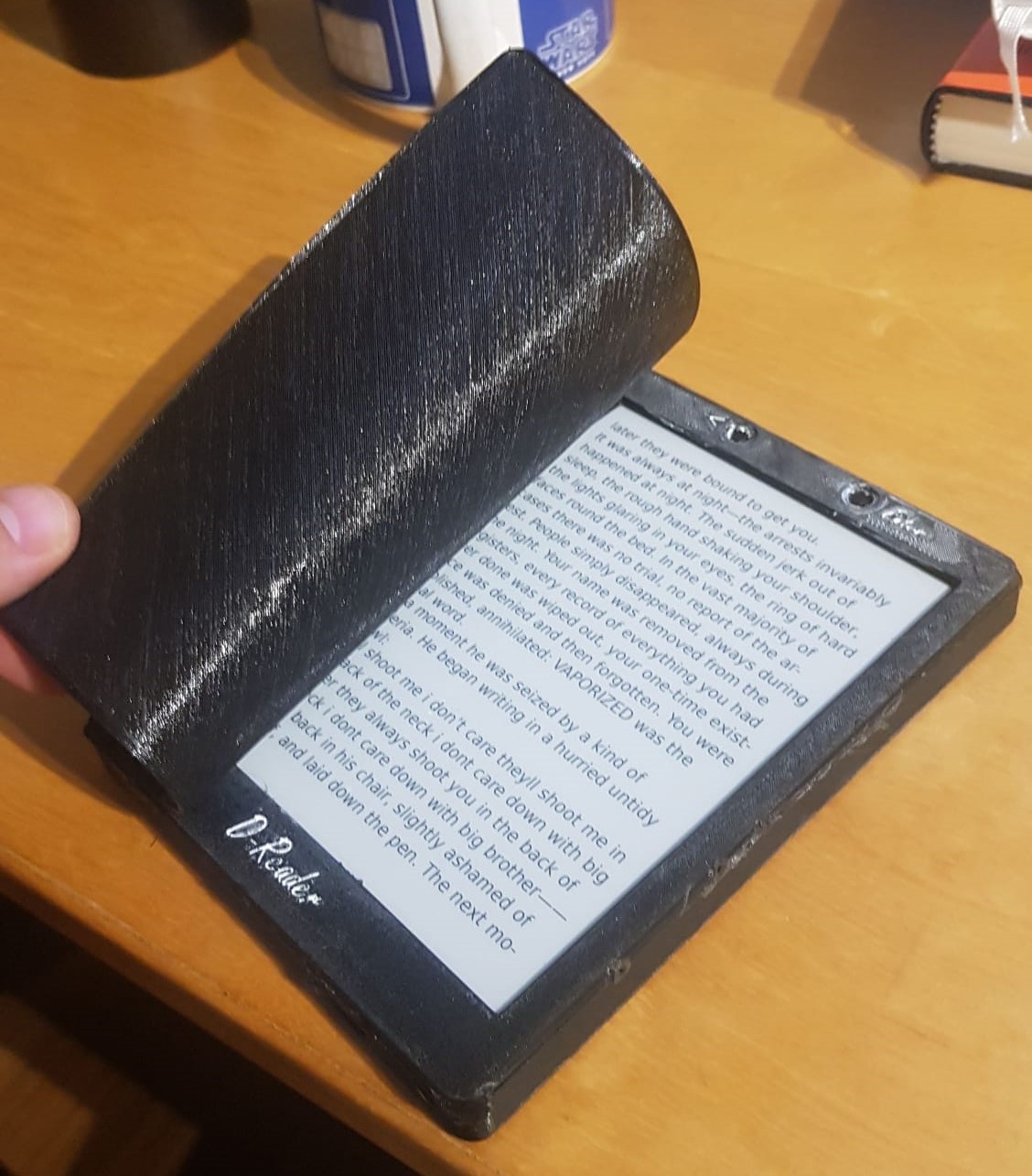
After selecting all the necessary parts, the next step was to start designing the ereader in FreeCAD. The final CAD model can be found in the CAD folder, which contains all the parts that need to be machined as well as the CAM jobs.
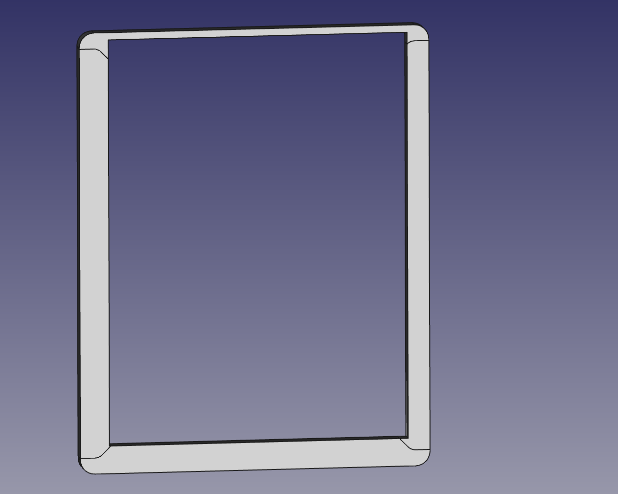
Since this was a re-housing of the electronics from the original device, most considerations on locations and dimensioning were already made. However, designing around the E-ink display had some interesting quirks. At the bottom of the e-ink display where the ribbon cables attach, there is a larger area that is not capable of showing an image, but which changes color when the display is activated. This triangular zone changes tone depending on what is displayed, and it may be where the display removes e-ink particles of specific colors to achieve higher contrast.
To avoid giving the reader cause for concern in both versions of the D-Reader, this zone was hidden behind the face, which requires a large thin overhang. The face itself is composed of 4 interlocking parts, with buttons and magnets for the cover embedded inside it.
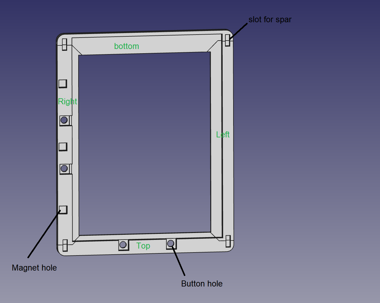
The body section was designed to seal in the buttons and magnets and to be glued across the joins, so the cut locations in the frame were adjusted to maximize overlap while not making the walls too thin.
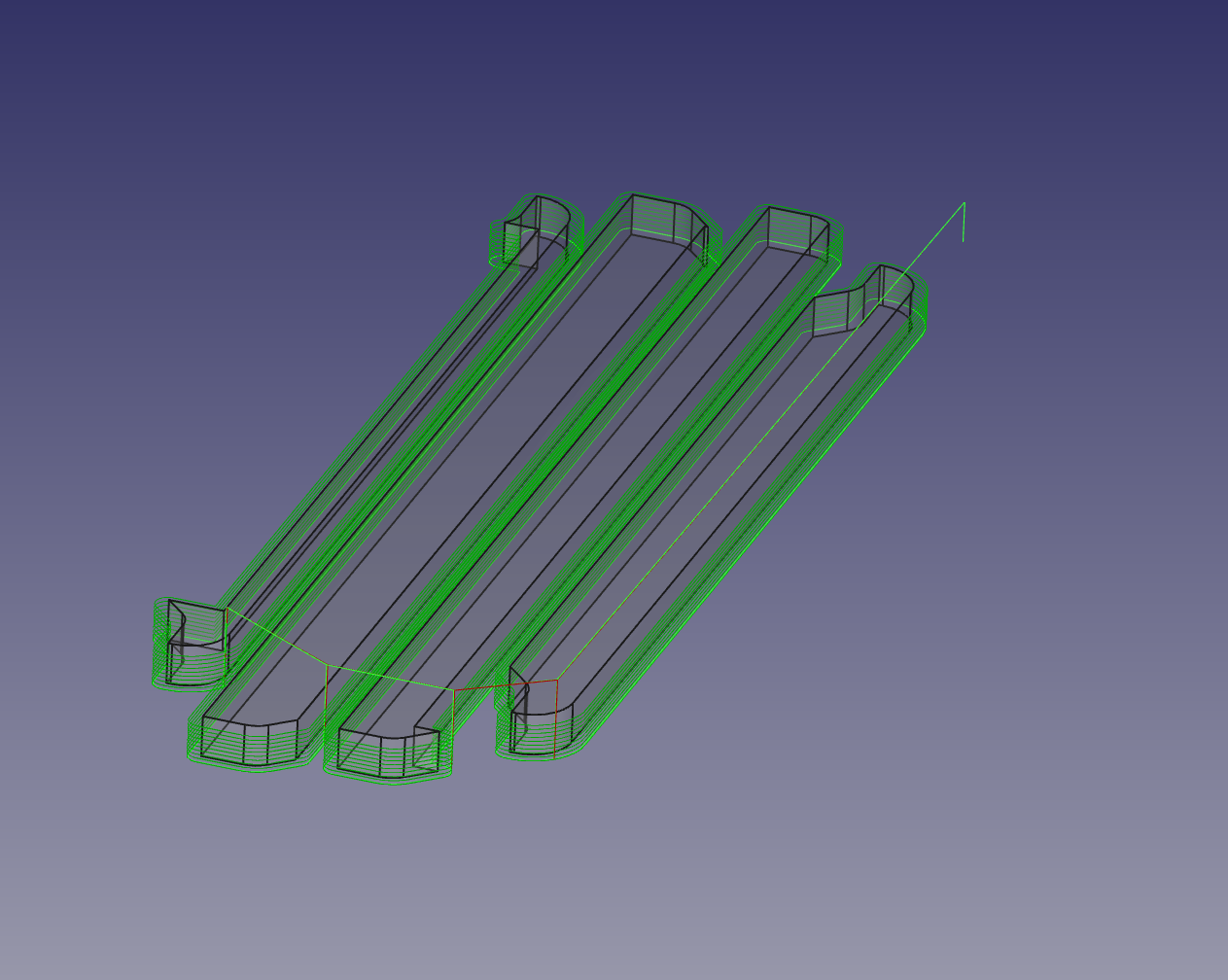
For the CNC job, the pieces were arranged in a material-saving way. The cuts were done with two passes, first a rough cut with 0.2mm offset and step downs of 0.75mm, then the final cut along the profile with the entire tool in contact with the wood. The boards were attached to the bed of the CNC using the age old CA and masking tape method, and cuts were made using a double-fluted down-cutting 3mm end mill.
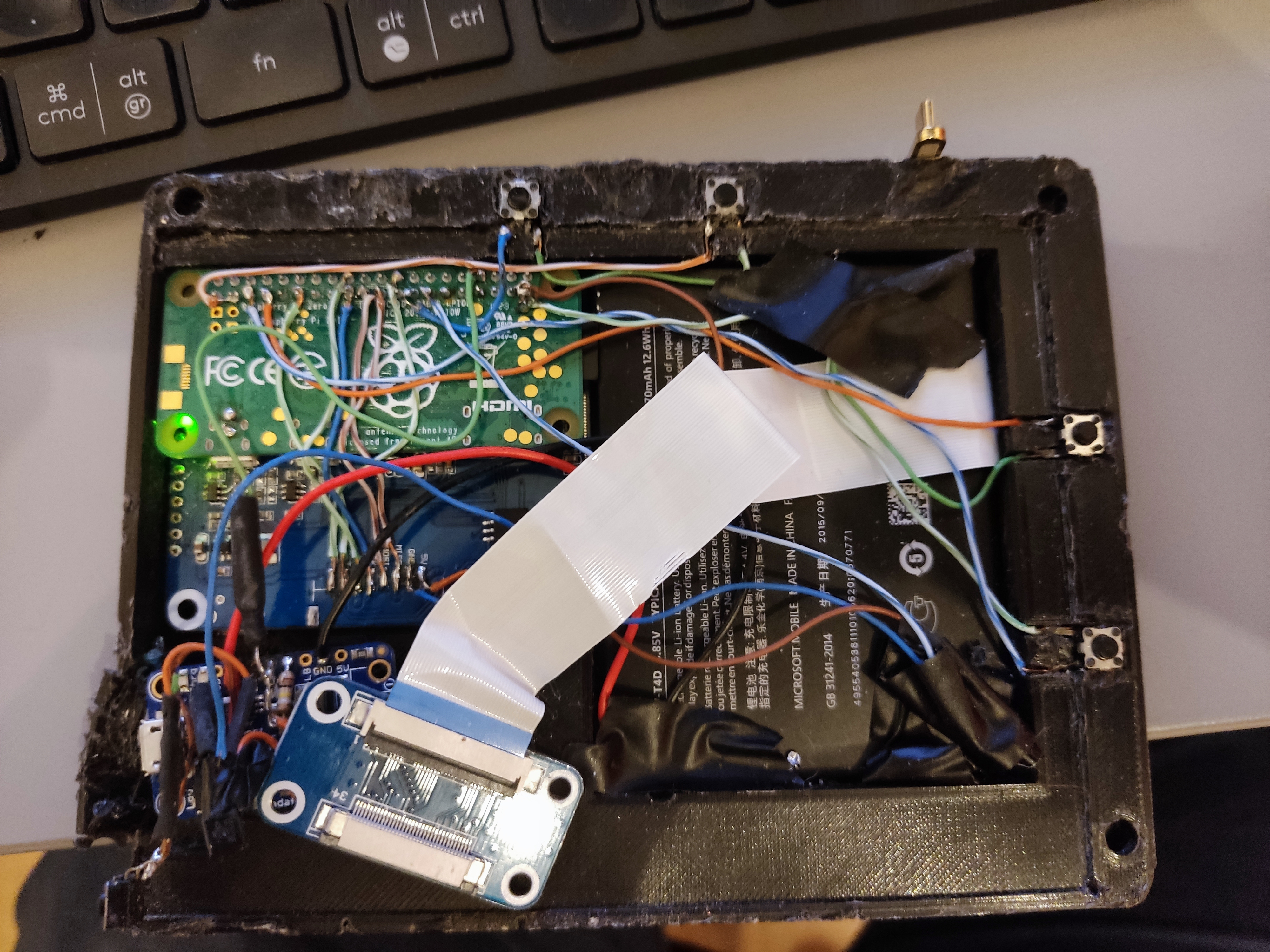
The assembly process was relatively straightforward. First, the cover and screen were assembled. A 1.2mm PLA plate was printed to match the size of the screen and was glued to the screen using epoxy. This was designed to reduce the chance of a point load causing the screen to locally bend and break. Once the screen was assembled, the electronics were added. For more detailed information on the electronics, see here.
Ereader Controller
The remote trigger for the ereader was designed in the form of a watch. The case and strap are a single print of TPU, with the closing mechanism for the strap being through a “hook” and hole system.
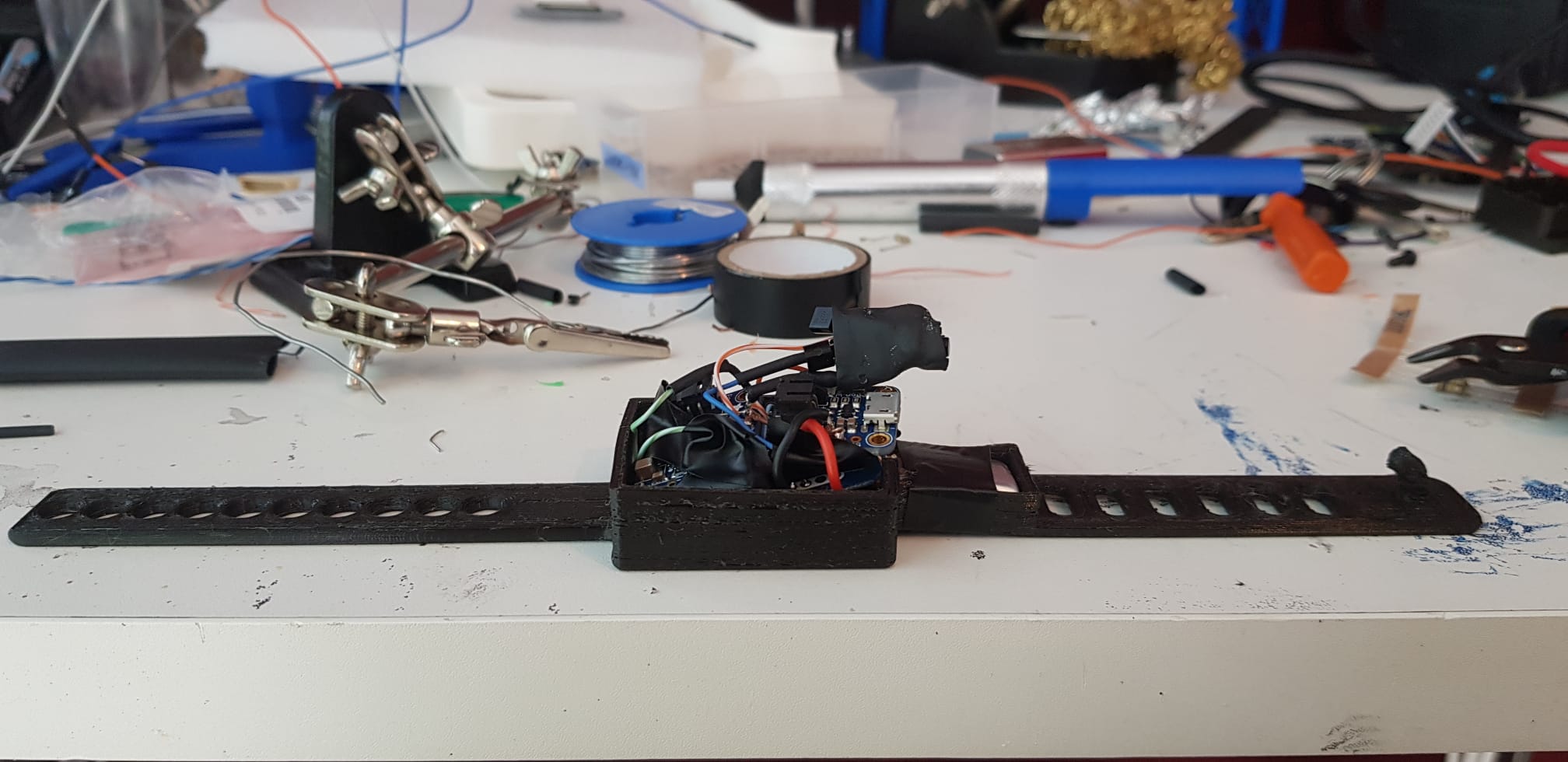
The case contained:
- ICM20948
- Wemos mini D1 esp32
- Adafruit boost basic 500C
- 250 mAh battery
- Adafruit Micro-Lipo Charger for LiPo
To reduce the size of the body unit, the battery was placed in a separate housing on the strap. The separation of the charging and boost units allowed the IMU and boost unit to be packaged side by side under the ESP32 board. On top of the ESP32, the charging circuit and power management buttons are located. The final packaging of the unit was done using black insulation tape to close the top of the print.
.jpg)
