Simplifying an E-reader’s Electro-technical Elements
Creating an electronic design for an E-reader was easy for a hobbyist because of the many 3.3v-5v modules and opensource libraries. The major challenge was fitting it into a reasonable form factor. Here are the essential electro-technical elements:
Waveshare IT8951 controller
This controller is a plug-and-play Raspberry Pi module that creates fantastic images. However, it’s not compatible with all Raspberry Pis because of their differing heights, resulting in hours of de-soldering and damage to the board. Additional wires had to be run between the boards.
Power Circuit
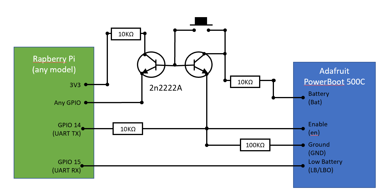
A PowerBoost 500C was used to charge the battery and provide 5V to the system. A circuit inspired by lipopi enabled a single button to be the on/off signal, copying the user experience of a Kindle. The TX of the RPI can enable the power boost once power is provided. More electronics allow an interrupt to the system when the same button is pressed again to initialize a shutdown signal.
User Input
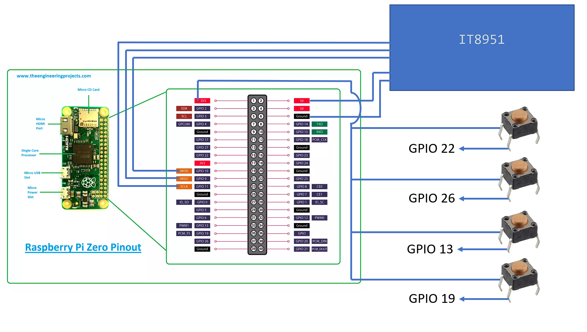
The IT8951 is connected via SPI and needs a 5V supply. The buttons are all connected to a 3v3 bus, and the output legs are connected to the listed GPIOs in pull down mode. There’s a 10k resistor between the 3v3 and the button bus to protect the system from high current draws and protect the GPIOs.
Packaging
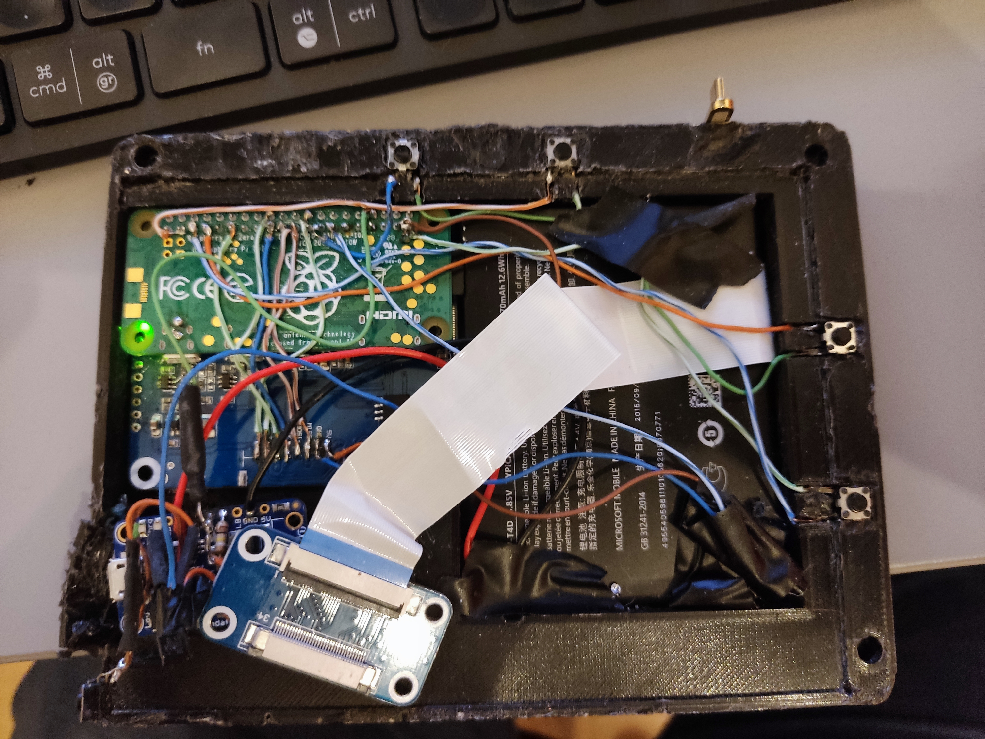
Packaging the electronics was not straightforward. An adapter was needed for the E-ink display ribbon cable to a second ribbon cable. The ribbon-ribbon adapter always stuck out beyond the screen, but a 45° to the screen ribbon and corrective 45° bend to the white ribbon solved this. The white ribbon was wrapped around the circuit boards and battery into a single bundle. Solid core copper cable from an old Ethernet cable was used for all connections not done by ribbon cable.
Controller
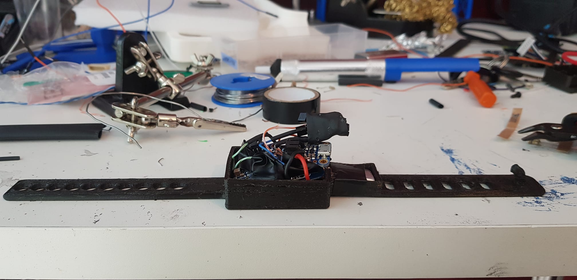
The remote trigger was designed in the form of a watch, using the following development boards:
- ICM20948
- Wemos mini D1 esp32
- Adafruit boost basic 500C
- 250 mAh battery
- Adafruit Micro-Lipo Charger for LiPo
The Adafruit boost and charger circuits function like a single boost charger, but two separate boards were used to create a lower profile package. The wiring of the power circuit was very similar to the LiPoPi inspired circuit of the e-reader itself. The IMU and ESP32 were connected via i2c.
.jpg)
