Heating control system
The second law of thermodynamics states “that the total entropy of a system either increases or remains constant in any spontaneous process; it never decreases.” Put in the context of heating a home the most you can hope for is the retain the heat through insulation (keeping the entropy between your house and the outside low), you will always loose the heat to the outside eventually.
This project was started during our first winter in the Netherlands. The radiators in our apartment were furnished with simple open/shut valves with little to no tuning possible, no thermostatic control. The increase in gas price during the pandemic caused my partner and I to experience a few shocks about the heating cost, this led me to think about how to tune the system to save us money.
The first step was solving an issue with the thermostat, this was a single Honeywell round thermostat with no clock for day/night timing and it was also mounted on probably the most poorly insulated wall of the house, so it would show a hybrid temperature of the outside and inside temperature. The thermostat uses OpenTherm to communicate with the boiler and also receive power (it’s a 2 wire for power and data protocol). After considering the consequences of damaging the boiler electronics I decided to avoid interfacing with it directly, so the solution was to mechanically control the thermostat.
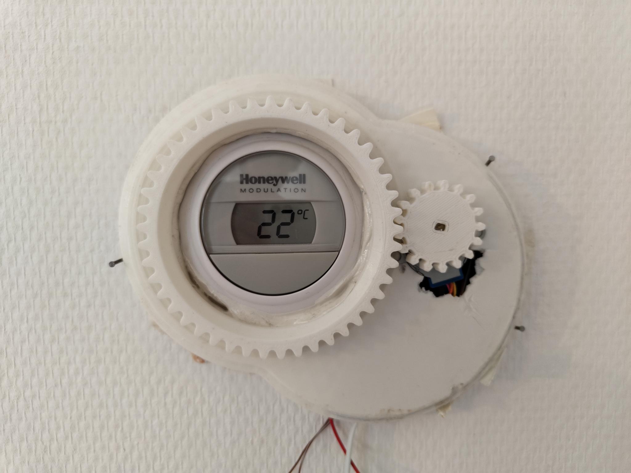
This involved printing a step-down gear system from a 28byj stepper motor to the thermostat. The motor was controlled by an ESP32 connected to an MQTT server. This allowed an MQTT message to set the thermostat value through mechanical manipulation of the thermostat rather than electronic. Also of note is that the boiler is turned either on or off by the thermostat there is nothing in between for fine tuning of temperature.
The next step in the process was to control the follow into the radiators. There were two versions of this created. A first version used some mini-servo motors to rotate the valve and were attached directly to the radiator.

There were 2 of this versions made but it suffered from a few design issues, firstly the servo motors were very loud, secondly connecting directly to the radiator allowed the PLA to warm up to a temperature where it become gummy and suffered from creep. Finally, the use of ESP-01s made it hard to debug issues occurring on the device, and there was limited IOs to connected something to monitor or log.
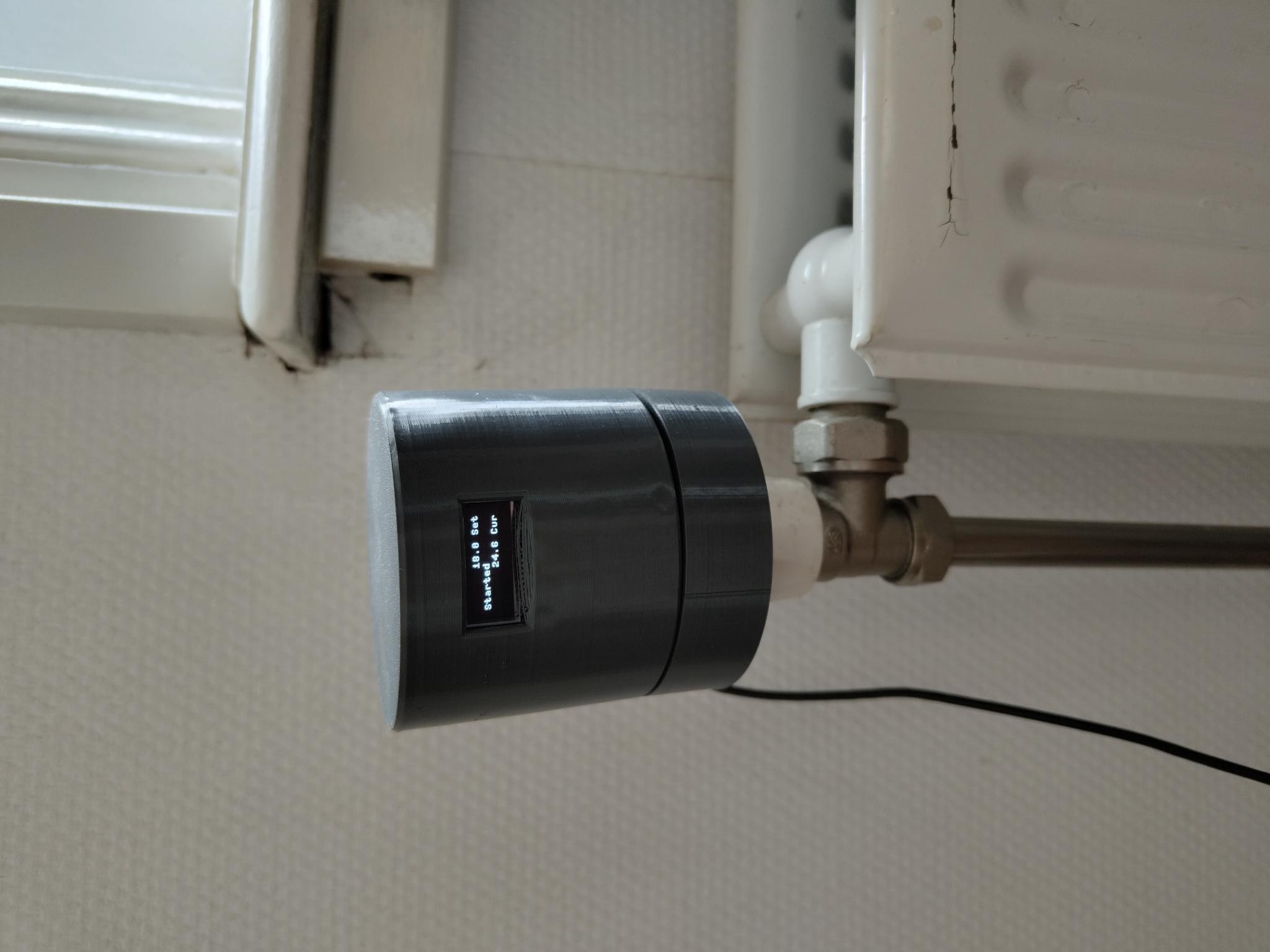
The redesign of for version 2 learnt from these lessons and used the same 28byj stepper motor as used to control the thermostat. This motor has very little torque, so it was coupled to a planetary gear box. To help debug issues a small oled binary display was added which printed information about the current state.
So, with these capable of actuating the system the next issues were sensing and controls.
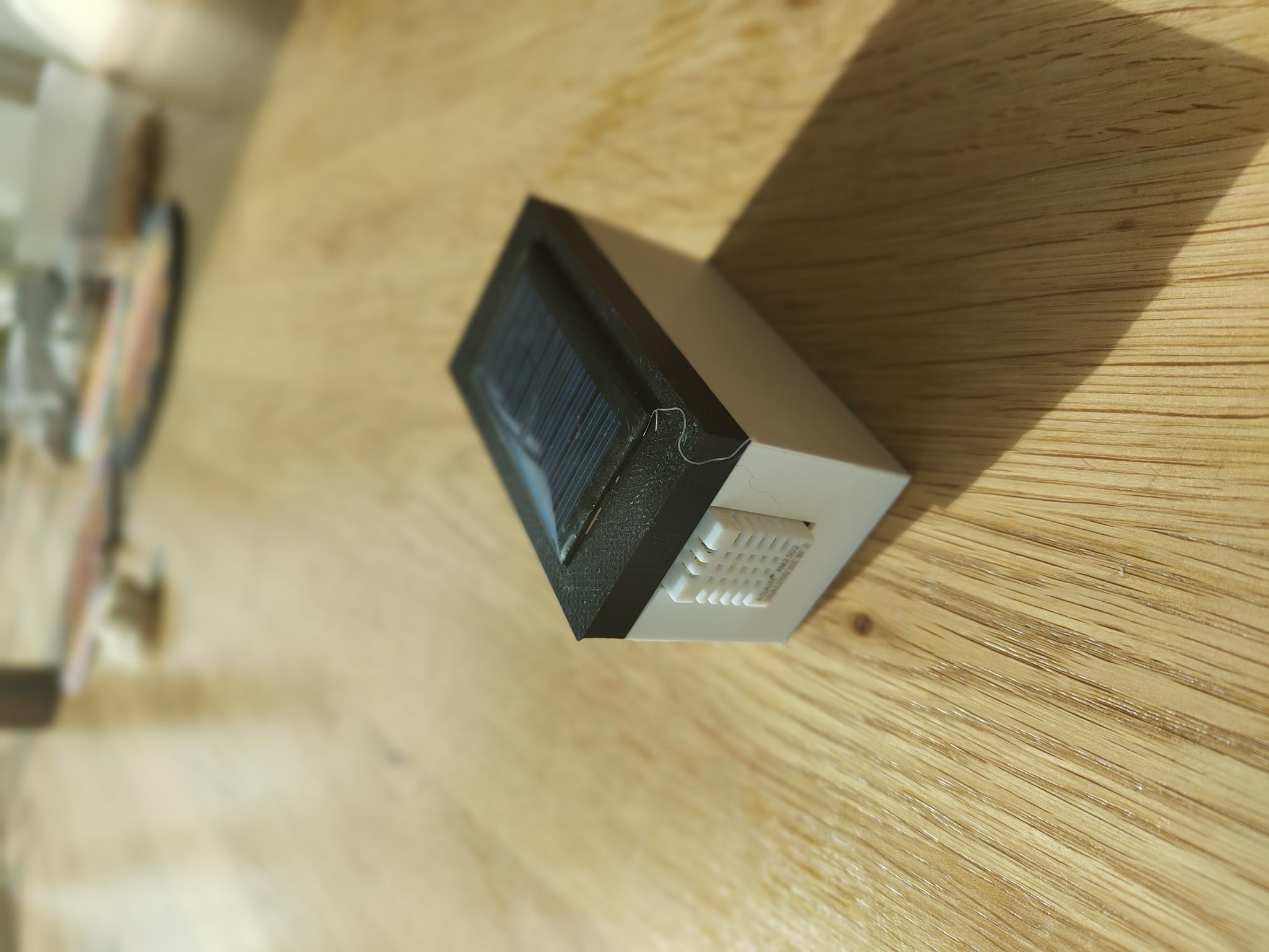
Sensing was very straightforward; this was done with an ESP32 connected to an DHT22. The ESP32 was in deep sleep for a minute before reading the sensor and again logging the temperature via MQTT. There were a few different electronic designs for this, first using ESP-01s with the deep sleep hack, but the possibility of reading with the ULP (the DHT22 has a 2 second warm up) then using the ESP32s main processor only for Wi-Fi based logging convinced me to switch boards. Sadly, I never got the ULP aspect fully working. However, the devices had ~2 months of battery and served their purpose well.
The control system was very straightforward, if the temperature in a room was bellow a set point it register that the boiler was needed and also open the valve to the radiator. If the temperature was above a second set point it would close the valve and also register that the boiler wasn’t needed. The server.py script allowed the number of rooms bellow their set points to be set before which the boiler would enable.
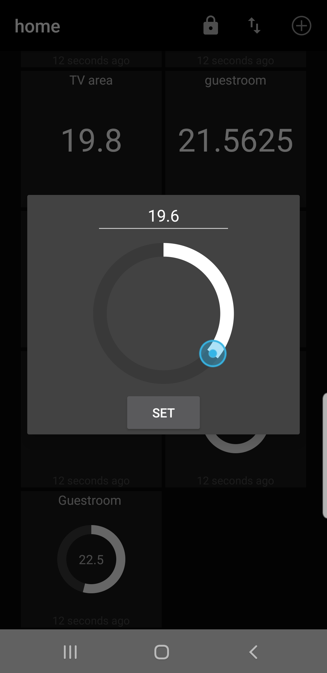
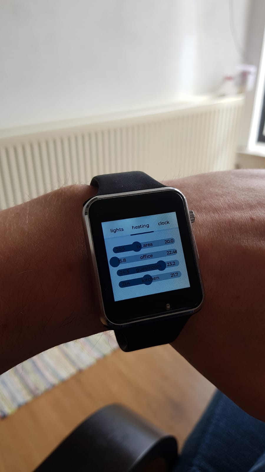
The set points were user determined either by an app or via a customized Lillygo 2020 watch.
This all comes together in the following system, where the connections between the elements are shown.
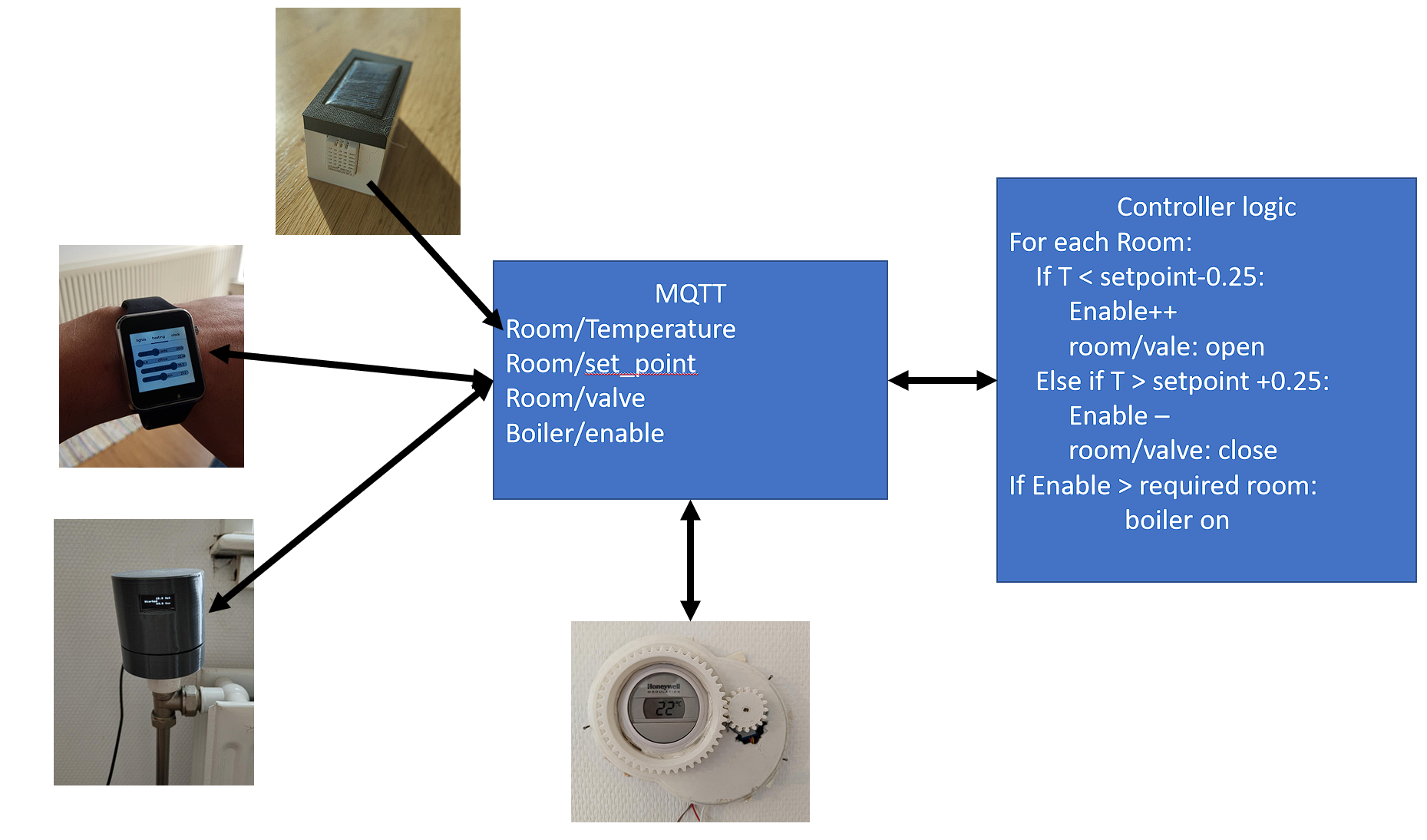
The thermometer has a unidirectional connection to the system, it simply sends the temperature (and humidity) to the MQTT server on a roughly 1 minute basis. The MQTT server is also connected to by the radiator_server.py script, which stores the values in a database (very useful for tuning the system) and also orchestrates the opening and closing of the valves and the activation of the boiler, again by posting to an MQTT server. The valves and thermostat listen to this MQTT server and behave accordingly, the thermostat also uses the MQTT server to store its state, so should it reboot it will reload the currently set value. The valves connect to show the set points and current temperature. Finally, the user can set the settings with either the watch or the android application.
A recording for a single room will look like this:
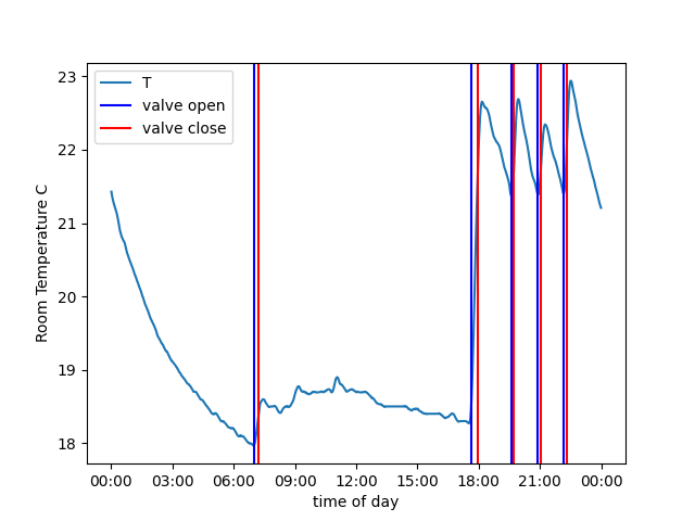
In the morning the system turns one at 7am and heats the room to the set point of about 18.5 degrees. This room likely wasn’t used that day until about 18:00 when the set point was evidently changed to about 21 degrees. The system can be seen opening and closing the valve, while the temperature overshoots by about 1.5 degree each cycle.
The same plot can be made for all rooms simultaneously.
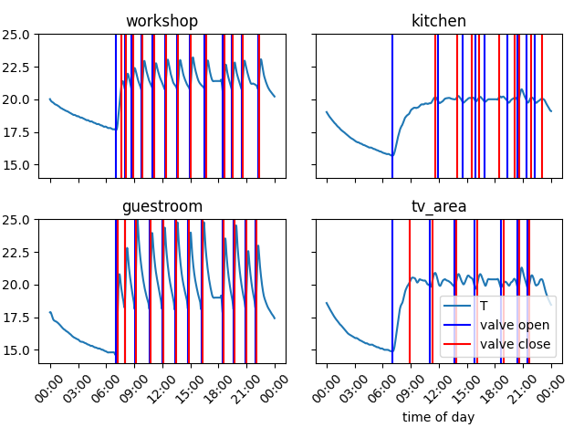
This is a recording of a typical day and the differences in the valve behaviour for the different rooms underlines the initial issue with the heating system. As the valves were not thermostatic some of the rooms would have been saunas with the heating make the coldest room comfortable, or the coldest room would have likely been below 16 degrees with the warmest at 21.
The other big advantage of the system was the ability to just turn down rooms that were not in use. This is an image from a weekend where lots of time was spend in the kitchen and watching TV.
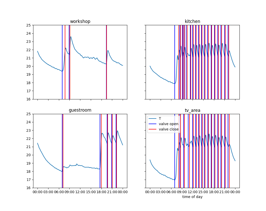
The guestroom and workshop have been turned down during the day and remain cool, or at least unheated. While the kitchen and tv area are warmed.
How to use this
building the devices
The devices are all 3d printed, the stl files can be found here, while for the devices designed in FreeCAD the drawings are here, I am more than willing to convert the missing drawings to FreeCAD if there is a request. All of the electronics rely on WEMOS ESP32 board, and 28byj stepper motor with drivers.
Radiator Valve
For the valve controller the following assembly is required.
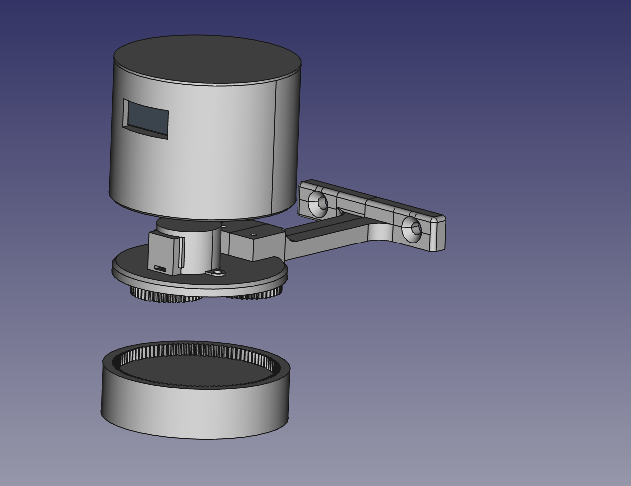
The motor and wall bracket should be mounted on the carrier base using m3 screw. The bracket might need to be pre-tapped depending on the printer settings. The ESP32 and stepper driver can be mated at the GPIO see here for port numbers. For the OLD display depending on the version used you will need to solder wires on with about 8cm in length. I used the cheapest version from amazon, and they worked fine. This also needs to be wired to the ESP32 for GPIO see here. The screen can then be secured in place within the upper case with scotch tape and/or glue. The ESP32 can be power via USB and the VCC of the board should be connected to the stepper motor. The planetary gear box should slot together, if it is a little tight then twisting it during assembly will help get it together. Using the ESP32 test the rotation of the gear box and the torque, a tight gear box might need some lubrication, also when applying a resistance check if the gears try to eject themselves from the gear box, if this happens it might be worth flipping some of the planet gears, as the 3d printing process might have left them tapered which causes them to push out of the ring gear.
The whole lower assembly can be mounted on the radiator valve, mark the holes on the wall for the wall bracket for drilling and attaching with rawlplugs and screws. Once the lower assembly is attached the upper case assembly can be seated in place. If needed some soft putty of scotch can be used to secure it in place.
It is worth taking time to measure the distance between the wall and the radiator valve, the adjust the wall bracket either by stretching the mesh or using the free cad file.
Thermostat control
The thermostat control was electronically very similar to the radiator valve, this consisted of a ESP32, in this case it was a raw module, which was all I had available, and I would recommend a WEMOS ESP32 or other such dev board, the software can be found here.
The assembly consisted of a case containing the electronics and the motor. While gears were attached to the motor and the thermostat. The thermostat gear was secured using white re-usable adhesive putty, while the drive gear was press fitted.
Thermometers
These used a DF Robot ESP32 Firebeetle board, connected to an DHT22, an 18650 battery, and a 30ma Solar panel. Unfortunately, I have not been able to track down the STL files and the original CAD files were made using an educational licensed Siemens NX. I am more than happy to re-create them in FreeCAD on demand.
Flashing the devices
All the devices run micropython, if the latest version does not work these were flashed with versions from spring 2021. Once the devices have micropython copy the source code across and make sure you convert the “example_settings.py” to a “settings.py”.
Setting up the server
This project runs on a Raspberry Pi, it is very light weight. There are some software requirements that your package manager can solve:
- mosquitto (or another MQTT broker)
- Python >3.5
- MariaDB
Once these are setup all you need to do make a “config.py” out of the example_config.py and run the main script. Ideally this script should be configured to run as a systemd module or a cronjob.
There will likely be teething issues, either from this software or from things overlook during the setup. The most likely source of problems is the firewall will be blocking MQTT and MariaDB when this first starts, check for your Linux distro how to open the ports. Another issue which might occur is if you do not provide the raspberry pi with a static IP address, if during reboot it loses its address this will be a huge pain, so ensure it is indeed static to start with. Finally, when the MQTT server restarts, it is advised to restart all the devices manually with a power cycle, they are configured to reconnect on failure but this is the safest option.